What is Relay in Electronics ?
A relay is an electromagnetic switch operated by a small electric current that can turn on or off a much larger electric current.Relays was invented in 1835 by American electromagnetism pioneer Joseph Henry in a demonstration at the College of New Jersey, Henry used a small electromagnet to switch a larger one on and off. that relays could be used for control electrical machines over very long distances.
Where Relay Use ?
- Used in to controlling heavy motors
- Commonly used in switching circuits.
- With Microcontroller use in Home Automation projects to switch AC loads
- To Control (On/Off) Heavy loads at a pre-determined time/condition
- Used in safety circuits to disconnect the load from supply in event of failure
What are the Different Types of Relay ?
Depending on the operating principle and structural features relays are of different types such as electromagnetic relays, thermal relays, power varied relays, multi-dimensional relays, and so on, with varied ratings, sizes and applications.
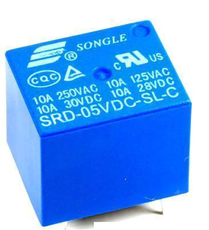
These relays are constructed with electrical, mechanical and magnetic components, and have operating coil and mechanical contacts. Therefore, when the coil gets activated by a supply system, these mechanical contacts gets opened or closed.Magnetic Latching Relays use permanent magnet or parts with a high remittance to remain the armature at the same point as the coil is electrified when the coil power source is taken away.
2.Solid State Relays
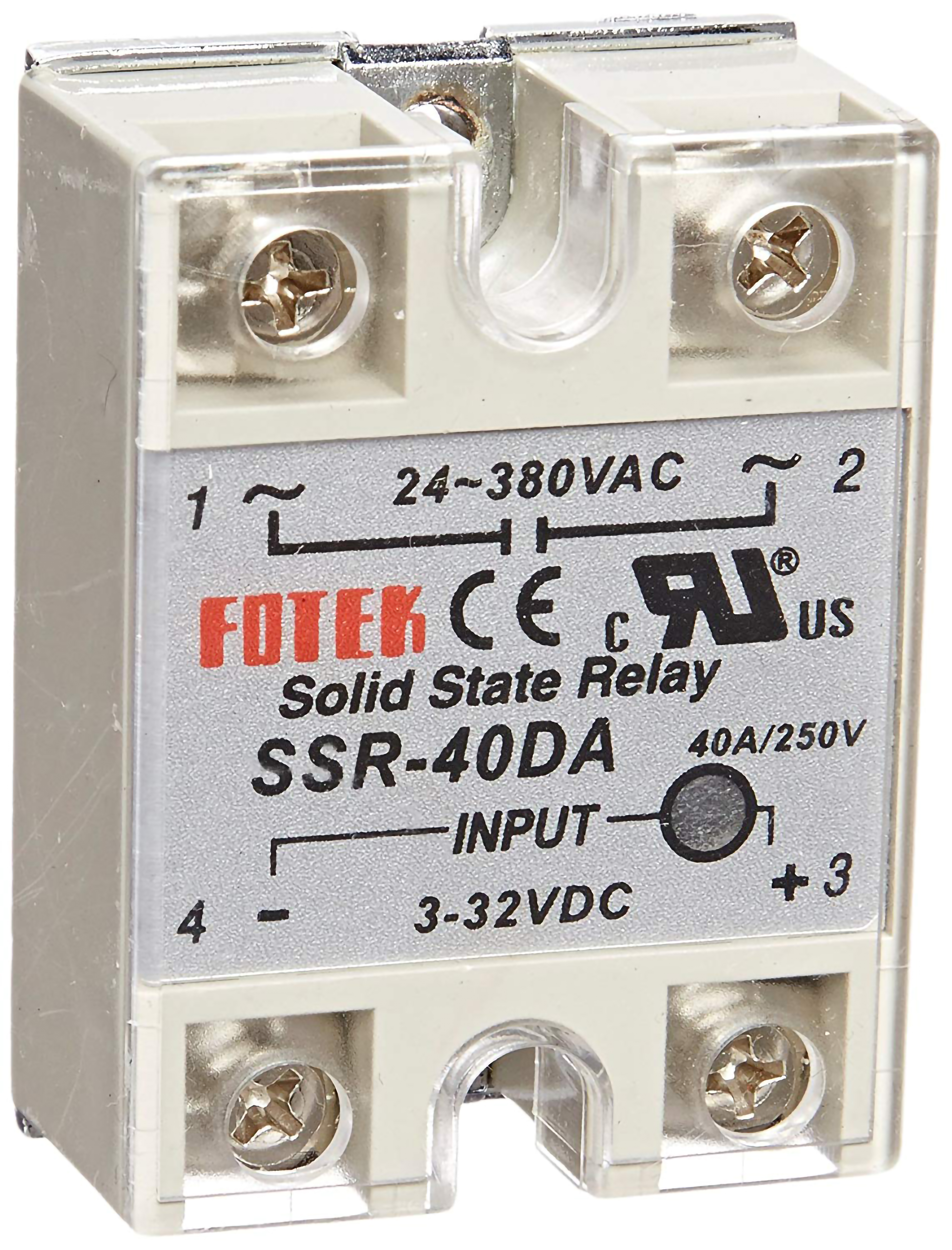
Solid State uses solid state components to perform the switching operation without moving any parts. Since the control energy required is much lower compared with the output power to be controlled by this relay that results the power gain higher when compared to the electromagnetic relays. These are of different types: reed relay coupled SSR, transformer coupled SSR, photo-coupled SSR, and so on.Solid State Relays has a photo coupled SSR where the control signal is applied by LED and it is detected by a photo-sensitive semiconductor device. The output form this photo detector is used to trigger the gate of TRIAC or SCR that switches the load.
3.Hybrid Relay
These relays are composed of electromagnetic relays and electronic components. Usually, the input part contains the electronic circuitry that performs rectification and the other control functions, and the output part include electromagnetic relay.
4.Thermal Relay
These relays are based on the effects of heat, which means – the rise in the ambient temperature from the limit, directs the contacts to switch from one position to other. These are mainly used in motor protection and consist of bimetallic elements like temperature sensors as well as control elements. Thermal overload relays are the best examples of these relays.
5.Reed Relay
Reed Relays consist of a pair of magnetic strips (also called as reed) that is sealed within a glass tube. This reed acts as both an armature and a contact blade. The magnetic field applied to the coil is wrapped around this tube that makes these reeds move so that switching operation is performed.
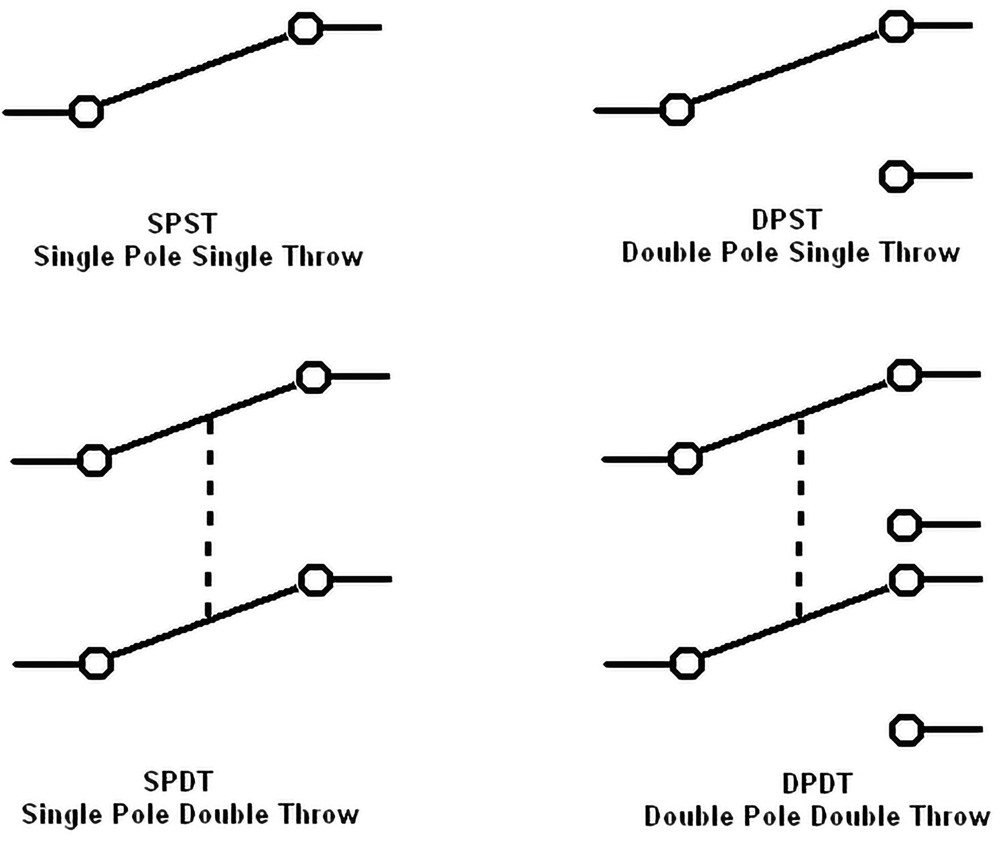
What are Relay with different Switching contacts ?
Switching contacts can be SPST, SPDT, DPST and DPDT types. Some of the relays are normally open (NO) type and the other are normally closed (NC) types.
Poles and Throws, Open and Closed
The number of poles * on a switch defines how many separate circuits the switch can control. So a switch with one pole, can only influence one single circuit. A four-pole switch can separately control four different circuits.
A switch’s throw-count defines how many positions each of the switch’s poles can be connected to. For example, if a switch has two throws, each circuit (pole) in the switch can be connected to one of two terminals.
Knowing how many poles and throws a switch has, it can be more specifically classified. Commonly you’ll see switches defined as “single-pole, single-throw”, “single-pole, double-throw”, “double-pole, double-throw”, which are more often abbreviated down to SPST, SPDT, and DPDT, respectively.
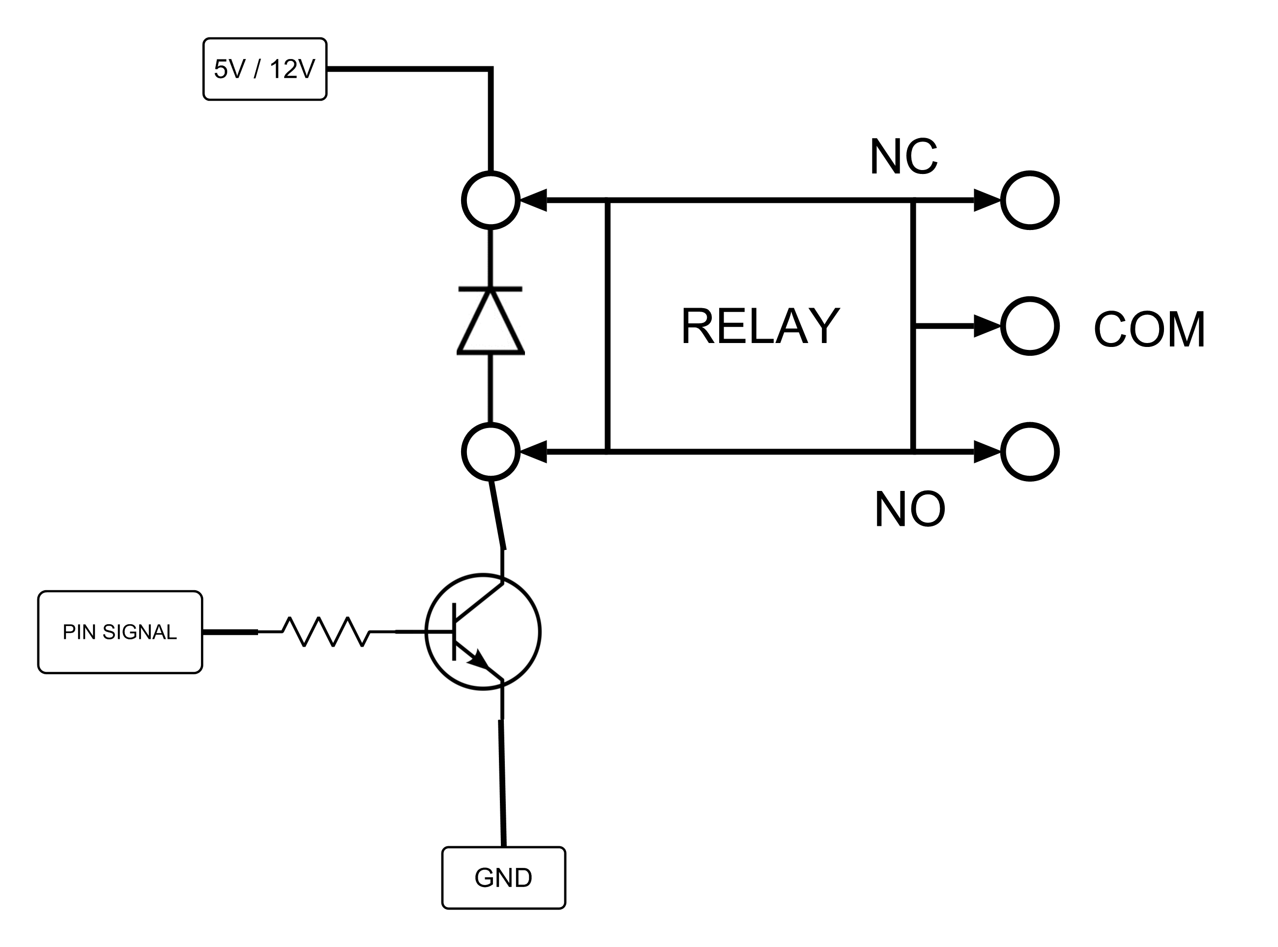
How Relay Works?
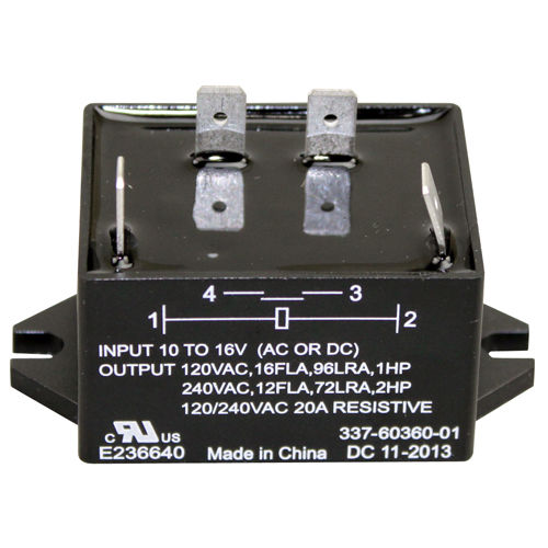
For Basic Use electro-mechanical Specification use in by Voltage / Current Amperes Holds.Like 5v operates 220v 10A,12v operates 220v 30A,12v operates 12DC 10A DC.
Basic parts and functions of electromechanical relays include:
Frame: Heavy-duty frame that contains and supports the parts of the relay.
Coil: Wire is wound around a metal core. The coil of wire causes an electromagnetic field.
Armature: A relays moving part. The armature opens and closes the contacts. An attached spring returns the armature to its original position.
Contacts: The conducting part of the switch that makes (closes) or breaks (opens) a circuit.
When a relays coil is energized by a current flow through the coil creates a magnetic field. Mostly used DC voltage use at one Side and Other Side is AC HIGH Voltage ( which Damage our Micro-controller if Power high Ac voltage). the magnetic coil is magnetize make its self a magnet which attracts a ferrous plate, which is part of the armature. One end of the armature is attached to the metal frame, which allow to move armature as a pivot, Armature is C ( Common) is moving Part.When the power not pass through Coil Armature is connected to NC Pole (Normal Connected / Normally Closed Circuit ).When we power coil magnetism happen Armature moves to NO (Normally Open) . Now here the common pole use connect AC power, by help of simple switch like one wire is connect to C pole (Common) . Then wire connect to NO is connect to Load .
In Case you no identified which is NC and NO you can also identified by using continuity tester from multimeter. Connect one probe of multimeter to common(C) and other to any one of the two leads on the opposite side. The one which gives continuity is Normally Closed(NC) and so the other is obviously Normally Open(NO).
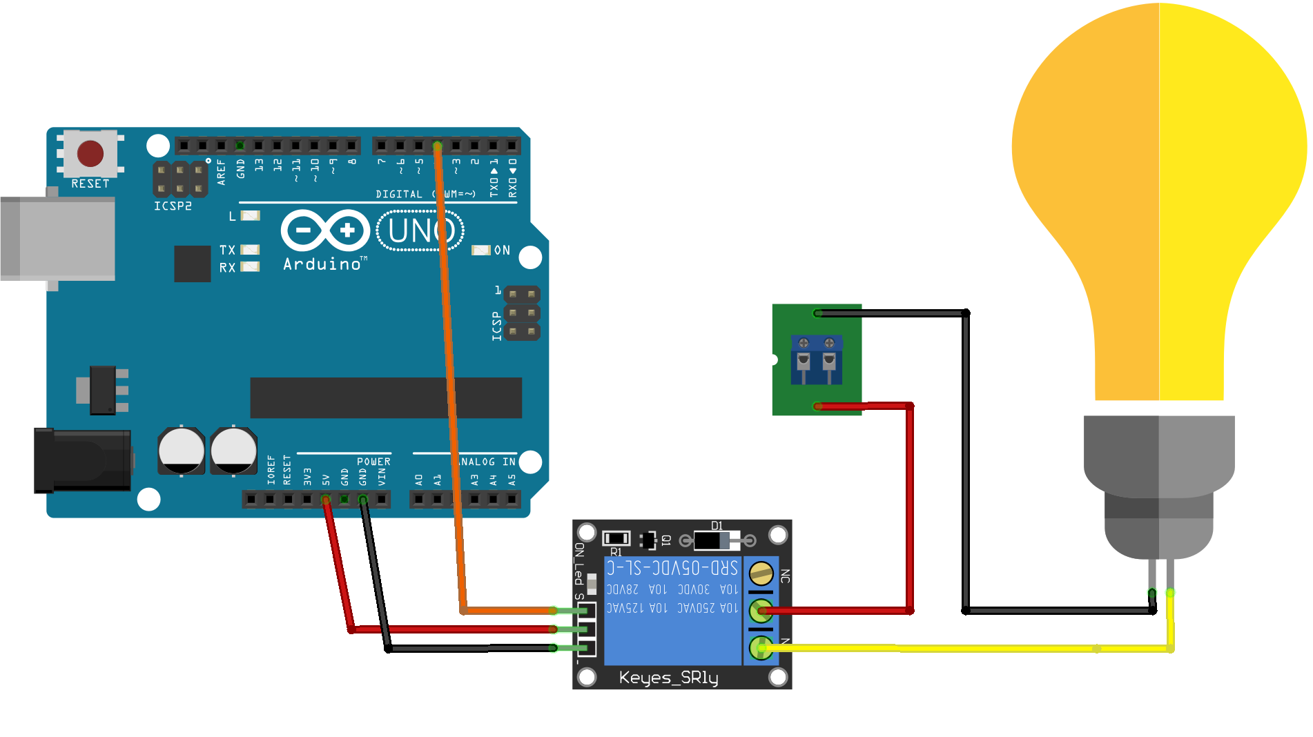
How to Use Relay with Arduino in own Circuit ?
Requirements List for make Own Relay Module.
- Relay 12v / 5v Any
- BC547 / BC548 / Optocoupler Ic
- IN4001-IN4007 Any Diode / Zener Diode
- 10K Resistance
- 12v power Adapter
- 220v Bulb Any
- High Voltage Wire 2.5 to 5mm Any